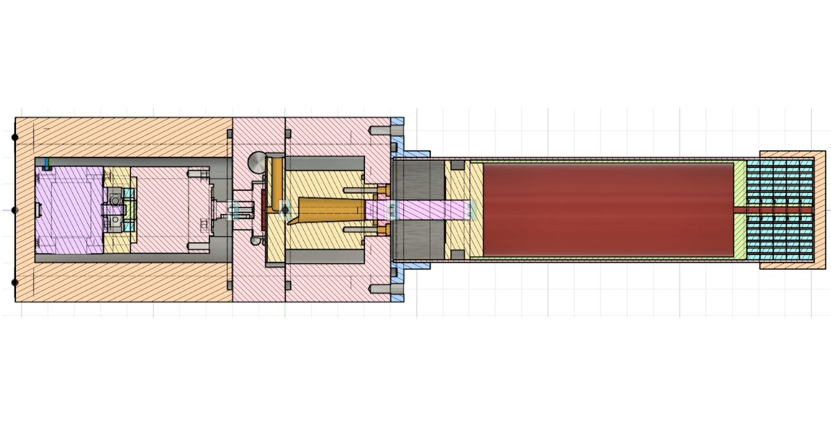
Over a decade ago, when I was in high school, I got it in my head that I wanted to figure out how to make liquid nitrogen. I’d seen some people on the internet doing so via the Joule-Thomson effect, and thought I might make it happen with the help of the air compressor in my garage
Obviously it didn’t work. I didn’t have the knowledge or the resources at the time to complete such a project.
I tried again briefly in college, with a friend, to build a pulse tube cryocooler. But we really didn’t do the required research and due diligence and our attempt barely cooled at all.
But over the years, my knowledge and capabilities improved, and I saw more evidence of the project on the internet. Applied Science and BenNBuilds, and later Veritasium and NileRed made videos on the project. And while they are all very interesting projects, they all seemed a bit more “how to buy a liquid nitrogen generator” than “how to build a liquid nitrogen generator”
The exception was Hyperspace Pirate, who was the only person I could find who was really trying to do the same project as me.
After seeing his videos, and then NileRed’s video, I was inspired again and decided to buckle down and truly design a custom cryocooler, accepting that there would be some expenses along the way. This is the design I came up with
Custom GM-Type Cryocooler
There are a few types of system that one might use to liquefy nitrogen, and I considered several of them:
- Joule-Thomson System – This might be the “easiest” system to build, but it basically boils down to buying a huge industrial-size air compressor and running it out a heat exchanger – not the DIY feel I was going for.
- Claude liquefier – Another industrial system, perhaps with a smaller compressor than Joule-Thomson but with an expansion engine. I wasn’t confident in my ability to build an expansion engine that would work at cryogenic temperatures.
- Traditional GM-type cooler – The simplest type of cryocooler on paper. It uses a modest-size external compressor, but has moving parts internally in the form of a moving displacer piston/regenerator. These are the most common in industrial/lab settings where a lot of cooling is required but the efficiency is not important.
- Pulse-tube GM-type cooler – Similar to the traditional GM cooler, but no moving parts in the cold head. Great on paper, but tuning the pulse tube could be very exact and challenging. I had tried this in college and didn’t have faith I could execute well.
- Stirling type coolers – These are the most common in “DIY” projects because they are small, self contained, and reasonably efficient. However, they require precise engineering and machining, and are quite complex. They require custom linear motors, resonant systems, gas bearings, etc to work effectively.
After this bout of research, I decided to go with a traditional GM type cooler. It had the fewest hurdles to overcome – just needing to move the displacer back and forth.
The operation of the system is pretty simple – I won’t describe it here, but there are good descriptions on Wikipedia or Hyperspace Pirate‘s videos.
Research
There is a lot of general information available on GM-type cryocoolers, but not a lot of details. Dimensions, materials and specifics are all lacking in the academic materials. To get an idea of dimensions, I looked to teardowns of commercial units. In particular, this one was useful.
With an idea of what to do, I went ahead and started designing. The design I will describe here is the final result after quite a few revisions, but I didn’t document the initial revisions very well. There are many things I learned through the process of iterating, and I will mention as many as I can.
Design
To size the cold head, I actually started with the compressor and worked backwards to dimensions. The compressor I planned to use was a GK113CAB, and based on the chamber size, charge pressure and pressure ratio, I picked some dimensions for the cold head. These dimensions are a bit of an educated guess on what should work.
The design I came up with looks like this – the whole thing is available on fusion for people who want to observe the design.
Fusion project: https://a360.co/49JFP3d

1. Motor and Feedthrough design
The rotary valve needs to be rotated to cause the pressure fluctuations that allow the system to cool. I did some back of the envelope math based on the sizing of the rotary valve, and found I may need in excess of 5 Nm of torque, and a rotation rate around 0.5 Hz. I also wanted to be able to control the position to adjust the phase relationship, so I wanted to use a stepper motor, and chose this geared stepper unit.

Ultimately, I did not use any of the stepper motor benefits, so it would be easier to use a geared DC motor of some sort.
The other complexity here is that the motor wires need to pass from the high pressure helium in the cylinder to the outside world where the controller is.
This ended up being challenging, because most products that achieve this are esoteric, expensive, or hard to get. At first I made my own using an NPT nipple, some 3D printed parts, and epoxy.


Each of these worked perfectly for about 24 hours, before quietly popping and dumping all of the helium. I switched to a PAVE 4760 after that, which costs $180 but works perfectly. I’m sure it’s possible to DIY this but I just wanted to get over this hurdle.

2. Rotary Valve and Manifold design
The rotary valve is the key to producing both the pressure oscillations in the cold head and the movement of the displacer piston. At first I thought this would be very difficult to design, but the design I settled on is actually quite simple.
The rotary valve consists of two interfacing parts, one I call the “valve disk” and the other the “valve block”


The parts are situated such that the valve disk is sitting in the high pressure reservoir, while most of the valve block is in the low pressure reservoir. a hole in the side of the valve block allows low pressure gas to connect with the hole in the center.
Thus, by spinning the valve disk we can connect the expansion volume and the piston to low and high pressure, at different times.

The ports on the valve block

The pressure zones in the valve portion of the cryocooler

The rotary valve sequencing
The high pressure on top of the valve disk forces it into the valve block, and helps to maintain a seal. The seals don’t have to be perfect here, but any leaks do need to be much small enough to be a tiny fraction of the total flow.
In terms of materials, I believe commercial units use a ceramic disk and a hardened steel block, to maximize life and minimize wear. For my design, it took a few iterations to get it right and I don’t know how to make a ceramic valve disk, so this design is mostly 3d printed.
Both parts are printed out of PETG with 100% infill, but the valve block has a steel sheet layer glued on top, which I just cut with hand tools. Both surfaces were lapped flat to 3000 grit, and that has worked very well. There is minimal wear to either part after several dozen hours of running.
3. Regenerator Piston
The regenerator is moved up and down via piston action, using the phase shift on the rotary valve

The design is quite simple – there is a 3/8″ shaft in the regenerator, which will pull it up if the piston pressure is low and the chamber high, or push it down if the piston pressure is high and the chamber low.
The regenerator weighs around 4 pounds, and I was designing for 300 psi high and 100 psi low, so originally I used a 1/4 inch shaft, which should give about 10 lb of pulling force. In reality, there was friction in the o-ring on the regenerator, and some stiction, as well as the gas flow resistance, so the regenerator sometimes wouldn’t move or would move too slowly.
I upsized the piston to 3/8″ and it is much better, but the transit time of the piston was still too slow. I eventually had to adjust the phases on the valve disk to get it to work properly, and that is why the valve timing is closer to 180° than it is to the theoretical 90°
I also had some issues with the piston binding, presumably because I didn’t build everything perfectly, so the shaft was not concentric with the main tube. I fixed that problem with a slight draft angle in the piston cylinder. Since I 3D print the piston cylinder, this was an easy adjustment to make and completely fixed the problem.
4. Regenerator
The regenerator is the single most important part of the cryocooler to get right, and took me the most iterations to eventually figure out. The resulting design is pretty simple and cheap.
The most important factors that I am aware of are these:
- The regenerator media must have a high surface area to allow maximum heat exchange with the gas. This is directly counter to #2.
- The regenerator should allow gas through with as little resistance as possible. This is directly counter to #1.
- The regenerator should have low thermal axial thermal conductivity
- All gas passing through the regenerator should pass through the media
- We want to minimize dead space – any gas that is not in the cold end during decompression is going to reduce the efficiency of the cooler
Here is how I addressed each issue:
Choice of regenerator media
If you read the literature, you will know that the regenerator is probably made up of metal balls, or metal mesh, maybe bronze, stainless steel, or lead, or fancy magnetic materials.
The easiest system to build seems to be a tube full of small balls. In reality, I had a hard time finding small balls for cheap. The best I initially found was #12 lead shot, which has a 1.2mm diameter. Seems pretty small.
I built a regenerator with these balls, and found a couple problems
- It is very heavy, and the piston system is having a hard time moving it up fast enough
- The flow is very good, but the cooling performance of the cryocooler was bad. The coldest temperature I was able to achieve with this regenerator was -100 C. I didn’t know how much of this had to do with the material vs dozens of other factors, but it wasn’t good enough
I had a suspicion that the regenerator media was the limiting factor, so I went back to the drawing board.
I was actually able to find a firm on Alibaba that would cut custom mesh discs, for reasonably cheap. I ordered 1000 pcs of 45 mm, 150 mesh stainless 304 discs. I only paid $70 shipped, which is an incredible price for custom pieces like this.
These disks were a huge pain to insert into the regenerator tube without folding or otherwise ruining them, but after a few hours I was able to do it
The performance gain from this was huge and immediate – the very first time I used this regenerator I reached liquid nitrogen temps.
While this was a resounding success, it still didn’t feel like an ideal solution to me, for these reasons:
- It involves getting custom mesh discs cut in China
- It’s very difficult to iterate, replace, or otherwise service
- The porosity was almost 70%, which seemed to me like it couldn’t be good for performance.
It was at this point that I randomly came across S-70 abrasive media in my search. This stuff is essentially just tiny steel balls, around 0.2mm in diameter, and it is very easy and cheap to get. This is the one I bought.
I built a regenerator with this stuff, and the performance was great. Slightly better cooling performance than the mesh discs, but much easier to assemble, replace, iterate, etc.
Axial conductivity
This design parameter is not to difficult to achieve – basically the only requirement is you can’t have any continuous metal in the axial direction. Mesh discs and metal balls both accomplish this – the contact areas between the discs or balls are very small and prevent most of the thermal flow in the axial direction. This requirement basically just prevents us from using a solid chunk of metal with a lot of holes drilled in it, which might otherwise be a good choice.
The tube that holds the media also needs to be considered. In the literature I’ve seen phenolic mentioned as a material, but I just used 3D printed PETG. Plastic is good in that it is not thermally conductive, and the strength requirements are not high.
I didn’t know if the PETG would have structural issues at liquid nitrogen temperatures, but it has been fine. Maybe in the long term the regenerator will shatter, but it hasn’t happened yet.
Gas sealing and dead space
Gas needs to pass through the generator, not around it. The easiest way to solve this is with an o-ring, and that’s what I did. I initially had two o-rings, but the friction was far too high, so I reduced it to one and it still seems to seal very well.
The gap between the regenerator and the wall was also a bit of an issue – if there is a gap here, that will be dead space that will reduce efficiency. But if there is no gap, there will be a lot of friction. Ultimately, I manually sanded down the diameter of the regenerator until it just barely fit, then I polished it to 3000 grit.
The fit of the regenerator in the piston is almost a seal in its own right, but it is very important to keep the leakage down, so we still use an o-ring. It’s also relevant that as the regenerator cools, it will shrink faster than the stainless tube. This will create a bigger gap as it cools, but the o-ring on the warm end will maintain a seal.
If the regenerator material shrank less quickly than the stainless tube, it would bind up as it cooled. Thankfully this is not a problem with PETG – just got lucky.
Final regenerator design
The final design is just a plastic tube, filled tightly with S-70 blasting media, with an o-ring (actually an x-ring) at the top, and a polished diameter.

I do need to use a bit of grease on the o-ring to keep the friction down, but I have just used a small amount of PFPE/PTFE grease and it hasn’t migrated to the cold end or been an issue. Ideally this would be a dry seal, but that is harder to accomplish.
The small tube at the cold end is for interfacing with the heat exchanger.
5. Cold tip
This is where the magic happens, and where the major design dimensions come into play.
Based on teardowns, I decided to go with a 2″ tube, with ~6″ regenerator and ~1″ expansion space. I don’t know how ideal these dimensions are – they were just a guess but they have worked quite well.

The tube is stainless, because it is strong, abrasion resistant, and can be brazed to copper or more stainless. The top flange and copper cold tip are attached with silver brazing.
The tube is subject to axial thermal conductivity, so we want to keep the walls as thin as possible, while still being plenty strong for the pressures involved. I am using 2″ OD x 0.049″ Wall x 1.902″ ID stainless 304 for this project.
The only other concern for the cold end is how we exchange heat between the helium and the copper tip. If there is not good thermal exchange here, then the helium will have to get much colder than 77K to allow thermal conduction, and efficiency will suffer greatly.
We want a heat exchanger system that forces the gas to pass through it, but doesn’t have much resistance or much dead space. Again, my design of this was a guess, but I had some copper disks machined with many small holes in them, which solder into the cold end in a stack


The gas that passes through the regenerator has to pass through the tube at the end, which forms a clearance seal inside these disks. Most of the gas will have to pass through these holes, exchanging heat with the copper.
I don’t know how effective or necessary this heat exchanger is, but the overall efficiency of the cooler has been good enough so I assume it is an effective design.
Results!
Once I had a working system, I moved on to tuning it and measuring its performance.

You need a helium compressor to run this thing, and converting my GK113CAB to a usable helium compressor is a whole other project that I may or may not write about, full of helium leaks and oil getting everywhere.


To run it, I just lower the cold end into a 10L dewar and let it run. I did a bunch of trial runs with different running frequencies and charge pressures, and found it performs best at about 1.2 Hz with as much charge pressure as possible. The most I’m comfortable running is 300 psi, which result in a high pressure of 375 psi and a low of 150 psi
I run the system for a known period of time, and weigh the dewar both before and after. In my best run I measured 2.68 kg of liquid air generated in 14 hours, or 191 g/ hr. The compressor is drawing about 1150W the whole time
We know the specific heat and heat of condensation of air, so we can calculate the heat lift at ~22 W. With 1150 W input, the efficiency is ~5.4% carnot, which puts us here the the plot:

Right in the middle of the GM section, right where we want to be.
Let me know if you have questions about the design or ideas to make it better/ more DIY friendly!